Skip to content
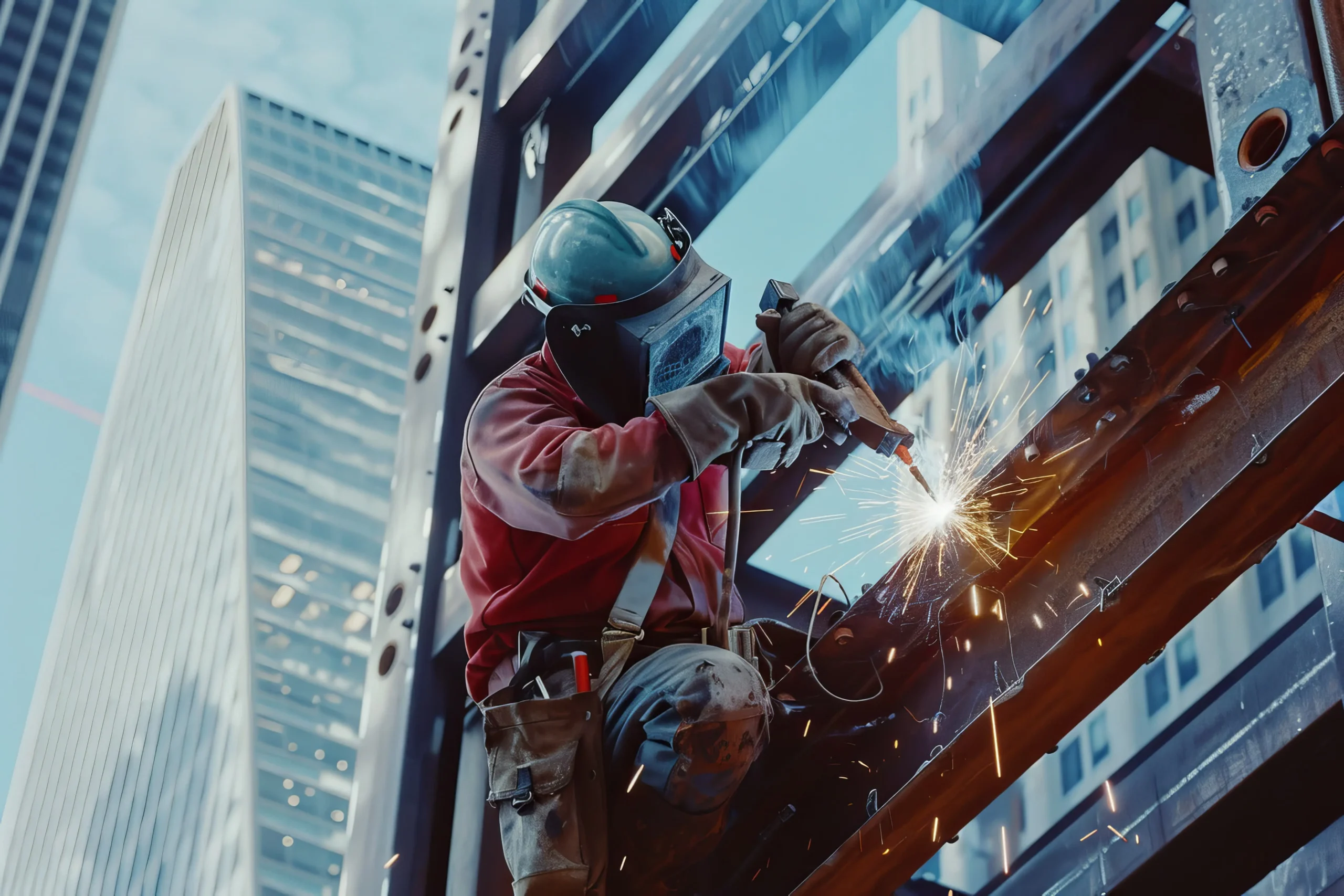
We’ve built our entire structural steel detailing workflow around Tekla Structures because it is the only BIM platform purpose-built for the tolerances, connection logic, and fabrication realities of structural steel. This article breaks down exactly why the software has become the benchmark for the industry — and why the detailing team behind the model matters just as much as the software itself.
What Makes Tekla Structures the Benchmark for Structural BIM
Tekla Structures is the industry standard because it models steel the way it is actually fabricated and erected — with real bolts, real welds, and real material properties — rather than as generic 3D geometry. That single distinction changes everything downstream: cut lists, NC files, bolt counts, and shop drawings all inherit accuracy directly from the model instead of being redrawn by hand.
Constructible Accuracy Over Generic 3D Modeling
Most general-purpose BIM tools treat a steel beam as a visual object. Tekla treats it as a fabrication-ready component with grade, camber, cope geometry, and connection hardware attached to it natively. When we change a beam size, every bolt group, base plate, and weld symbol tied to that member updates automatically. This is the difference between a model that looks right in a rendering and one that builds right on a shop floor.
Real-Time Clash Detection and Model Collaboration
Tekla’s collaboration environment lets structural, architectural, and MEP models sit inside the same coordinate system. We catch duct-to-beam conflicts, missed penetrations, and elevation mismatches before a single piece of steel is cut — not after a crew discovers it 40 feet in the air. For fabricators juggling tight erection sequences, that early clash resolution routinely saves weeks of field rework.

How Tekla Structures Powers Modern Structural Steel Detailing
Structural steel projects rarely involve one type of steel. A single job might combine primary framing, secondary bracing, stairs, and roof decking — and Tekla Structures is built to detail all of it inside one coordinated model rather than as disconnected drawing sets.
From Miscellaneous Steel to Complex Connections
Handrails, stairs, ladders, and platforms carry their own code requirements and fabrication tolerances, and they’re frequently where drawing packages fall apart. Our miscellaneous steel detailing process runs through the same Tekla model as the primary structure, which means a stair stringer and its supporting beam are never detailed in isolation — they’re solved together, with shared geometry and shared tolerances.
Joists, Decking, and Secondary Steel Elements
Roof and floor systems introduce their own coordination challenges: joist bearing seats, deck bearing widths, and header/trimmer conditions all need to align with the primary steel model down to the fraction of an inch. Our steel joist and deck detailing work is modeled directly against the framing, so bearing conditions are verified inside Tekla rather than cross-checked manually against a separate drawing set — a step that eliminates one of the most common sources of field bearing conflicts.

The Business Case: Why Fabricators Choose Tekla-Based Detailing Partners
For a shop owner or project manager, the software behind a detailing package isn’t an abstract preference — it directly affects schedule, material waste, and RFI volume.
Faster Shop Drawing Turnaround
Because Tekla generates drawings, NC data, and material lists directly from a single model, revisions don’t require redrawing multiple sheets by hand. A connection change updates the shop drawing, the erection drawing, and the bill of materials simultaneously. For fabricators working against aggressive delivery windows, that speed is often the deciding factor in choosing a detailing partner.
Reduced RFIs and Field Rework
RFIs are expensive. Every clarification request stalls a crew, delays a pour, or holds up steel delivery. Because Tekla models carry real connection geometry and real member properties, ambiguity is engineered out of the drawing set before it ever reaches the field. Fewer assumptions on paper translate directly into fewer questions on site.
| Detailing Approach | Drawing Accuracy | Revision Speed | Clash Detection | Field RFIs |
|---|---|---|---|---|
| 2D CAD-only detailing | Manual, error-prone | Slow — redraw per sheet | None | High |
| Generic 3D BIM software | Moderate | Moderate | Limited | Moderate |
| Tekla Structures detailing | Fabrication-grade | Fast — model-driven | Full 3D clash checks | Low |
Connection Design Precision Inside Tekla Structures
Connections are where structural engineering and fabrication reality meet, and they’re where the most costly detailing errors occur.
Engineering-Grade Connection Modeling
Tekla’s connection library isn’t decorative — it applies real bolt patterns, weld sizes, and plate thicknesses based on the parameters we input, and it flags geometric conflicts automatically. Our connection design process uses this engine to verify that every shear tab, moment connection, and base plate meets the specified capacity and physically fits within the surrounding steel — before the drawing package ever leaves our team.
How the Model Becomes a Fabrication-Ready Drawing Set
A common misconception is that Tekla simply “draws steel.” In practice, the platform generates shop drawings, erection plans, and NC/DSTV files directly from the 3D model’s geometry and connection data. We’ve documented how Tekla Structures generates fabrication-ready output from a single coordinated model, and it’s this generative workflow — not manual redrafting — that keeps our deliverables consistent across a project’s full drawing set.
Choosing the Right Tekla Detailing Partner for Your Project
Owning Tekla Structures licenses is not the same as detailing steel correctly in it. The software provides the framework; the accuracy still depends on the detailer’s understanding of connection design, fabrication tolerances, and code requirements. When we evaluate a project, we look at three things before modeling begins: the governing connection standard (AISC, CISC, or a project-specific spec), the fabricator’s shop capabilities, and the erection sequence — because a model built without those inputs, however clean it looks, will still generate drawings that don’t match how the steel gets built.
That’s the standard we hold every detailing package to, and it’s why fabricators come back to us project after project rather than treating detailing as a commodity service.
Frequently Asked Questions

Is Tekla Structures better than AutoCAD for steel detailing?
For structural steel specifically, yes. AutoCAD produces 2D drawings without inherent fabrication logic, so every revision has to be redrawn manually. Tekla Structures models steel as fabrication-ready components, generating drawings, NC files, and material lists from a single 3D source — which cuts both errors and turnaround time.
Do I need to own Tekla Structures to receive Tekla-based detailing?
No. Fabricators and engineering firms don’t need their own Tekla license to work with us. We handle the modeling and detailing on our end and deliver standard outputs — PDF shop drawings, DXF/DWG files, and NC data — in whatever format your shop already uses.
How long does Tekla-based structural steel detailing typically take?
Timelines depend on tonnage, connection complexity, and how many trades need to be coordinated in the model, but Tekla’s model-driven workflow generally shortens revision cycles compared to 2D detailing. We provide a project-specific schedule after reviewing structural drawings and connection requirements.
Conclusion

Tekla Structures earned its position as the industry standard because it models steel the way it’s actually fabricated and erected, not as an abstraction that gets reinterpreted at every stage of the drawing process. Combined with a detailing team that understands connection design, tolerances, and shop realities, it produces drawing packages that reduce RFIs, shorten revision cycles, and keep steel moving on schedule.
If you’re evaluating a detailing partner for an upcoming project, we’re ready to review your structural drawings and scope a Tekla-based detailing package built around your fabrication and erection sequence.