Skip to content
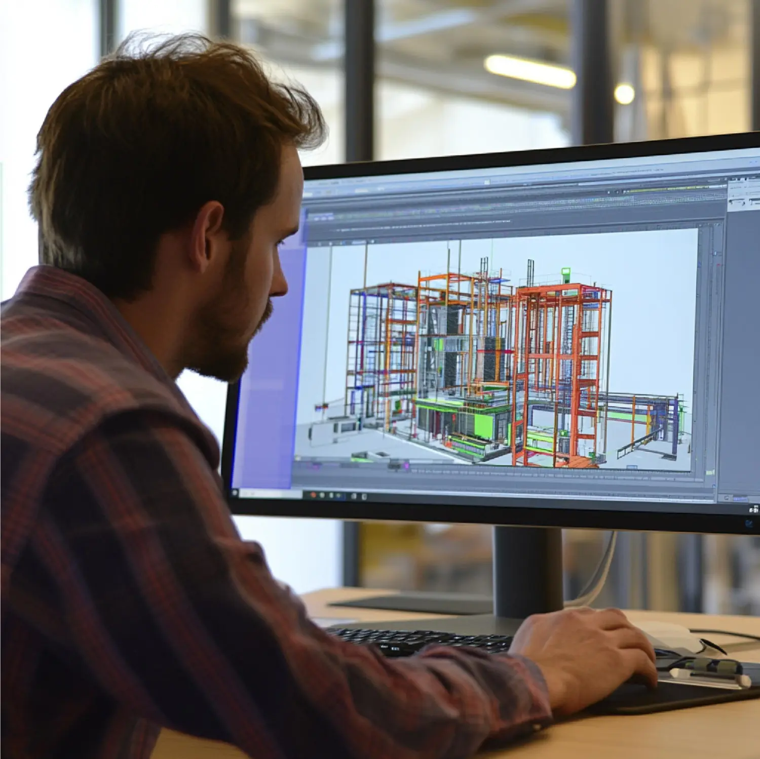
A shop drawing package is only as good as the model behind it, and that’s where most detailing services fall short. Generic 3D modeling can produce a beam that looks correct in isometric view but still misses bolt clearances, bearing tolerances, or connection capacity once it reaches the shop floor. Tekla-based steel detailing services close that gap by building accuracy into the model itself, so every drawing, cut list, and NC file that comes out of it reflects what can actually be fabricated and erected.
We rely on Tekla Structures as the core of our detailing services because it’s the only platform that treats a steel model as a constructible asset rather than a visualization tool. This article covers how that accuracy is achieved across a project, from raw structural steel through connections, miscellaneous elements, and secondary framing.

Why 3D BIM Accuracy Determines Project Outcomes
In steel fabrication, model accuracy directly controls fabrication cost, schedule reliability, and field rework — a Tekla model that’s off by a fraction of an inch on a bolt hole can stall an entire erection sequence. Unlike drafting software that only records what a drawing shows, Tekla Structures stores real material properties, connection logic, and physical clearances inside the model, so errors surface during modeling instead of during erection.
Parametric Modeling vs. Static 2D Drafting
A static 2D drawing has no memory of the geometry behind it — change one dimension, and every related view has to be manually corrected. Tekla’s parametric components work differently: a change to a beam’s size, grade, or position automatically propagates through every connection, bolt group, and drawing view tied to it. This is the core reason Tekla-modeled structural steel detailing holds up better under revision cycles than CAD-based alternatives.
Tolerance Control at the Model Level
AISC and CISC tolerances aren’t footnotes in a Tekla model — they’re built into how components snap, bolt, and clear one another. We set tolerance rules once at the project level, and every connection generated afterward inherits them, which removes the guesswork that shows up when tolerances are applied manually, drawing by drawing.

Core Steel Detailing Services Built on Tekla Structures
Accuracy isn’t limited to primary framing. A complete detailing service has to carry the same modeling standard across every steel component on a project, or the weakest piece in the package becomes the bottleneck in the field.
Primary and Secondary Structural Framing
Beams, columns, girders, and braces form the backbone of the model, and everything else — stairs, joists, connections — is detailed against them. Getting this layer accurate first is what allows every downstream detailing service to stay coordinated instead of drifting out of alignment as the project grows.
Miscellaneous and Architecturally Exposed Steel
Stairs, rails, ladders, and platforms are frequently the most labor-intensive elements to detail because they combine structural requirements with architectural finish tolerances. Our miscellaneous steel detailing service keeps these components inside the same Tekla model as the primary structure, so a handrail post and its supporting beam are checked against each other automatically rather than reconciled by hand later.
Joist, Deck, and Roof System Coordination
Bearing seats, deck attachment points, and header conditions have to match the primary steel down to fractions of an inch, or the roof system won’t sit correctly once it reaches the site. Our steel joist and deck detailing work is modeled directly against the framing components rather than as a standalone drawing set, which is what allows bearing conflicts to be caught before fabrication instead of during a field fit-up.

How Connection Modeling Drives Detailing Accuracy
Connections are the single largest source of RFIs and rework in structural steel projects, and Tekla’s connection engine is built specifically to model them with engineering-grade precision rather than as generic drawn symbols.
Automated Bolt Patterns and Weld Sizing
When we input a connection type — shear tab, moment connection, base plate — Tekla applies the governing bolt pattern, plate thickness, and weld size based on the parameters we set, and flags any geometric conflict with surrounding steel automatically. Our connection design process runs every connection through this check before a drawing is released, which is a meaningfully different standard than manually verifying clearances sheet by sheet.
From Model Geometry to Fabrication-Ready Output
The model is the deliverable — the drawings are just one output of it. Shop drawings, erection plans, bolt lists, and NC/DSTV files for CNC fabrication equipment are all generated directly from the same 3D geometry, which keeps every document in a package internally consistent. We’ve detailed how Tekla Structures generates these fabrication-ready outputs from a single coordinated model, and it’s this generative process — not manual redrafting between sheets — that eliminates the mismatches common in split drawing sets.
Where Detailing Accuracy Creates Business Value
For fabricators, accuracy isn’t a technical nicety — it shows up directly in bid margins, schedule performance, and repeat business.
| Detailing Standard | Bolt/Weld Accuracy | Revision Handling | Fabrication Output | Typical RFI Volume |
|---|---|---|---|---|
| Manual 2D drafting | Operator-dependent | Redraw per revision | Manual takeoff | High |
| Basic 3D modeling | Moderate | Partial automation | Manual export | Moderate |
| Tekla-based detailing services | Engineering-verified | Model-driven, automatic | Direct NC/DSTV generation | Low |
Lower RFI volume alone justifies the investment for most fabricators: fewer clarification requests mean fewer stalled crews, fewer delayed pours, and fewer change orders eating into project margin. Accuracy at the modeling stage is what protects schedule at the erection stage.
What to Expect From a Tekla Detailing Partnership
A detailing service is only as reliable as the process behind it. Before we begin modeling, we confirm the governing connection standard for the project, review the fabricator’s shop equipment and capabilities, and map the planned erection sequence — because those three inputs determine how the model needs to be built, not just how it needs to look. Skipping that step is how “accurate-looking” models still end up producing drawings that don’t match how steel gets fabricated in practice.
That process discipline is what separates a Tekla detailing service from simply owning Tekla software, and it’s the standard we apply to every project regardless of tonnage or complexity.
Frequently Asked Questions

What makes Tekla Structures more accurate than other detailing software?
Tekla models steel components with real material properties, connection logic, and physical clearances built in, rather than as static drawn geometry. Because drawings, cut lists, and fabrication files are all generated from that same model, accuracy carries through every output instead of being reintroduced manually at each stage.
Can Tekla detailing services handle both primary steel and miscellaneous steel in one project?
Yes. Primary framing, connections, stairs, rails, and secondary elements like joists and decking are all modeled inside the same coordinated Tekla file, which is what allows these components to be checked against each other automatically rather than reconciled as separate drawing packages.
How does 3D BIM modeling reduce fabrication costs?
Accurate 3D modeling catches clashes, tolerance issues, and connection conflicts before fabrication begins, which reduces rework, material waste, and RFIs. Because NC and DSTV files are generated directly from the model, fabrication equipment also receives more consistent data, reducing setup errors on the shop floor.
Conclusion
Accuracy in structural steel detailing isn’t a byproduct of using Tekla Structures — it’s the result of a modeling process that treats every beam, connection, and secondary component as a fabrication-ready asset from the first step. When primary framing, miscellaneous steel, joists, decking, and connections are all built inside one coordinated model, the drawings, cut lists, and NC files that come out of it stay consistent with each other and with what actually gets built in the field.
If your next project needs a detailing partner that holds that standard, we’re ready to review your structural drawings and scope a Tekla-based detailing package around your fabrication and erection requirements.